Showing posts with label Automobile Industry. Show all posts

Saturday, 1 February 2014

Why Manual Transmission Cars Make a Loud Whirring Noise in Reverse?

Manual transmissions use mostly helical gears, but reverse is a special situation that requires a different type of gear - a spur gear.

The gears that make up the forward gear ratios are all helical gears. The teeth on helical gears are cut at an angle to the face of the gear. When two teeth on a helical gear system engage, the contact starts at one end of the tooth and gradually spreads as the gears rotate, until the two teeth are in full engagement. This gradual engagement makes helical gears operate much more smoothly and quietly than spur gears. Also, because of the angle of the gear teeth, more teeth are in engagement at any one time. This spreads the load out more and reduces stresses.


The only problem with helical gears is that it is hard to slide them in and out of engagement with each other. On a manual transmission the forward gears stay engaged with each other at all times, and collars that are controlled by the shift stick lock different gears to the output shaft (see How Manual Transmissions Work for details). The reverse gear on your manual transmission uses an idler gear (the large spur gear visible at the right side of the picture below), which has to slide into mesh with two other spur gears at the same time in order to reverse the direction of rotation.

Spur gears, which have straight teeth, slide into engagement much more easily than helical gears, so the three gears used for reverse are spur gears>
Each time a gear tooth engages on a spur gear, the teeth collide instead of gently sliding into contact as they do on helical gears. This impact makes a lot of noise and also increases the stresses on the gear teeth. When you hear a loud, whirring noise from your car in reverse, what you are hearing is the sound of the spur gear teeth clacking against one another!

Thursday, 30 January 2014

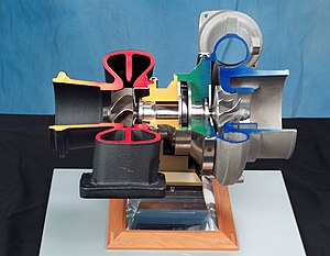
Turbocharger

01-twin turbo-supercharger and turbo 

A turbocharger is actually a type of supercharger. Originally, the turbocharger was called a "turbo super charger." Obviously, the name was shortened out of convenience.
01-Twincharger_theory-turbocharger layout diagram
A turbocharger’s purpose is to compress the oxygen entering a car’s engine, increasing the amount of oxygen that enters and thereby increasing the power output. Unlike the belt-driven supercharger that is normally thought of when one hears the word "supercharger," the turbocharger is powered by the car’s own exhaust gases. In other words, a turbocharger takes a by-product of the engine that would otherwise be useless, and uses it to increase the car’s horsepower.

01-turbo-parts-turbocharger section-compressor air discharge

Cars without a turbocharger or supercharger are called normally aspirated. Normally aspirated cars draw air into the engine through an air filter; the air then passes through a meter, which monitors and regulates the amount of air that enters the system. The air is then delivered to the engine’s combustion chambers, along with a controlled amount of fuel from the carburetor or fuel injectors.
In a turbocharged engine, however, the air is compressed so that more oxygen will fit in the combustion chamber, dramatically increasing the burning power of the engine. The turbocharger is composed of two main parts: the compressor, which compresses the air in the intake; and the turbine, which draws the exhaust gases and uses them to power the compressor. Another commonly used term in relation to turbochargers is boost, which refers to the amount of pressure the air in the intake is subjected to; in other words, the more compressed the air is, the higher the boost.
Although the increase in power is advantageous to the car — and likely a source of enjoyment for the driver — a turbocharger has its drawbacks. First and foremost, a turbocharged engine must have a lower compression ratio than a normally aspirated engine. For this reason, one cannot simply put a turbocharger on an engine that was intended for normal aspiration without seriously undermining the life and performance of the engine. Also, a lower compression ratio means the engine will run less efficiently at low power.
Another major drawback of a turbocharger is the phenomenon known as turbo lag. Because the turbocharger runs on exhaust gases, the turbine requires a build-up of exhaust before it can power the compressor; this means that the engine must pick up speed before the turbocharger can kick in. Additionally, the inlet air grows hotter as it is compressed, reducing its density, and thereby its efficiency in the combustion chamber; a radiator-like device called an intercooler is often used to counter this effect in turbocharged engines.

Turbo lag

Turbo lag is the time required to change power output in response to a throttle change, noticed as a hesitation or slowed throttle response when accelerating from idle as compared to a naturally aspirated engine. This is due to the time needed for the exhaust system and turbocharger to generate the required boost. Inertia, friction, and compressor load are the primary contributors to turbo lag. Superchargers do not suffer this problem, because the turbine is eliminated due to the compressor being directly powered by the engine.
Turbocharger applications can be categorized into to those that require changes in output power (such as automotive) and those that do not (such as marine, aircraft, commercial automotive, industrial, engine-generators, and locomotives). While important to varying degrees, turbo lag is most problematic in applications that require rapid changes in power output. Engine designs reduce lag in a number of ways:
  • Lowering the rotational inertia of the turbocharger by using lower radius parts and ceramic and other lighter materials
  • Changing the turbine's aspect ratio
  • Increasing upper-deck air pressure (compressor discharge) and improving wastegate response
  • Reducing bearing frictional losses (e.g., using a foil bearing rather than a conventional oil bearing)
  • Using variable-nozzle or twin-scroll turbochargers
  • Decreasing the volume of the upper-deck piping
  • Using multiple turbos sequentially or in parallel
  • Using an Antilag system
  • Using a turbo spool valve to increase exhaust gas flow speed to the (twin-scroll) turbine

Boost threshold

The boost threshold of a turbo system is the lower bound of the region within which the compressor operates. Below a certain rate of flow, a compressor produces insignificant boost. This limits boost at a particular RPM, regardless of exhaust gas pressure. Newer turbocharger and engine developments have steadily reduced boost thresholds.
Electrical boosting ("E-boosting") is a new technology under development. It uses an electric motor to bring the turbo up to operating speed quicker than possible using available exhaust gases. An alternative to e-boosting is to completely separate the turbine and compressor into a turbine-generator and electric-compressor as in the hybrid turbocharger. This makes compressor speed independent of turbine speed. In 1981, a similar system that used a hydraulic drive system and overspeed clutch arrangement accelerated the turbocharger of the MV Canadian Pioneer (Doxford 76J4CR engine).
Turbochargers start producing boost only when a certain amount of kinetic energy is present in the exhaust gasses. Without adequate exhaust gas flow to spin the turbine blades, the turbo cannot produce the necessary force needed to compress the air going into the engine. The boost threshold is determined by the engine displacement, engine rpm, throttle opening, and the size of the turbo. The operating speed (rpm) at which there is enough exhaust gas momentum to compress the air going into the engine is called the "boost threshold rpm". Reducing the "boost threshold rpm" can improve throttle response.

Key components of a turbocharger

The turbocharger has three main components:
  1. The turbine, which is almost always a radial inflow turbine
  2. The compressor, which is almost always a centrifugal compressor
  3. The center housing/hub rotating assembly
Many turbocharger installations use additional technologies, such as wastegates, intercooling and blow-off valves.


Wednesday, 3 April 2013

Monday, 1 April 2013

KAIZEN Philosophy: -


 KAIstands for “change” and ZEN stands for “improvement”.
So KAIZEN means, “Continual change for improvement”. This is the activity, which is open for all the employees, and all the employees take keen interest in this activity. “The more the number of Kaizens in a department, the more is the honor for the same” makes this event very much interesting.

Monday, 25 March 2013

RESEARCH METHODOLOGY


This methodology will explain how I went about doing my project. It is divided into two sections Sampling details & Data collection + analysis. In this there will be explanation of what kind of sample data I have taken for my project and the collection of that data.


SAMPLING AND DATA COLLECTION:

For the completion of my project I went through the random sampling of data. In which I have picked up some components randomly for the observation and did the analysis as required for the project. Photographs were taken and relevant readings were recorded for documentation & project report.
Data collection includes all the relevant and appropriate data required for the completion of the project. This is of two kinds, Primary data and Secondary data. Primary data includes all the data which I have collected from the crankcase line such as component flow path, dent prone areas on the cover & joint faces, dimensions of the cone plugs and actual dents on KSPG components during the trial PP1 before the mass production of this new model. Some data was collected from the metallurgical lab after hardness inspection of cone plugs and some data was collected from engine assembly.
Apart from this I have also used some data from the department itself as a secondary data. It includes the quotations from vendors, process sheets, PQCS-I & II, plug cone drawings, operation standards, defect flow sheets etc. This collection has been shown in the annexure attached ahead.                                  
These all were the samples that I have taken for the study to complete my project in a better way. I decided to choose this study material from our company itself because this was best and comprehensive according to the executives and the line leaders who themselves have designed it so far. So it was very easy for them to teach me about that. Also it is very clear from the fact that the current documentation is better because the production target was getting achieved very well.


1) THE PDCA APPROACH: -

Among the most widely used tools for continuous improvement is a four-step quality model-the plan-do-check-act (PDCA) cycle, also known as Deming cycle or Shewhart cycle.


Plan- Identify an opportunity and plan for change.
Do- Implement the change on a small scale.
Check- Use data to analyze the results of the change and determine whether it made a       
difference.
Act-If the change was successful, implement it on a wider scale and continuously assess                 
your results. If the change did not work, begin the cycle again.


this approach were incorporated while implementing the countermeasures. It helped in the uninterrupted

flow of project activities. It is a result oriented methodology with side by side analysis of the result. It helps as a perfect effectiveness and improvement monitor. It provides us with appropriate ideas and concrete steps to avoid failures. It is a complete
quality analysis + control package with minimum discrepancies. That is why it is sometimes referred to as root cause of all improvements.
As a whole the PDCA methodology was of immense help during my stint of seven months as an industrial project trainee.     

Wednesday, 6 March 2013

MARKET DETAILS OF AUTOMOBILE INDUSTRY:-


Automobile Industry is one of the few industries which have shown a continuous rapid growth since the industrial revolution in early 20th century. Also it has grown within itself, with the no. of manufacturing companies and types of vehicles increasing every year. Indian automobile industry is no exception with most of the major companies of the world investing in INDIA. With the Indian economy on boom, even the domestic companies are making rapid strides and competing with the international ones. The dramatic influence that automakers have on global economy is one of the indications of how widespread and significant this industry has become.
                                  The globalization of the Indian automobile industry continues, and their collaboration with foreign companies is flourishing. Gradual changes in the Indian economy and rising disposable income of the people is resulting in increased motorization. Global connections are seen as an effective way to respond to this trend, and will continue to multiply as the world’s automobile industries try to meet the increasing demands in a growing number of markets.
The main reasons for this exponential growth and revolution in Indian automobile industry (especially two-wheelers) are:-


  1. Government’s initiative on rural roads and better connectivity with major towns and cities.
  2. Improved agricultural performance.
  3. Upward trend of purchasing power in the hands of rural people.
  4. Better understanding between the world economies resulting in free and easy trade.
  5. Increasing trend of cooperation between world class companies in the field of automobile industry with an approach to reduce the costing.